Cardiovascular diseases are a significant health concern, with high mortality rates.
Electrocardiographic (ECG) signals are a primary screening method for heart conditions.
The lecture poses the question: Can we perform automated analysis of ECG signals to recognize different types of arrhythmias like tachycardia, bradycardia, atrial fibrillation, etc.?
Can we differentiate arrhythmias based on automated signal analysis, for example, by looking at their periods?
II. Core Questions & Introduction to “Fourier Time”
Representation: Can we represent a periodic signal as a sum of periodic signal components, each with a different period?
Component Definition: If so, how should we define each component?
The answer lies in Harmonically Related Complex Exponentials (HRCE).
Component Strength: How do we know the strength of each component in the periodic signal?
This involves the definition and evaluation of Fourier series.
Applicability: Is this applicable to all periodic signals or just a specific class?
This relates to the convergence of Fourier series.
III. Complex Exponentials as the Building Block
Why not just impulses? Convolution uses impulses to decompose signals.
Inefficiency of Impulses: For infinitely long signals (like periodic signals), using unit impulses is inefficient.
x(t)=∫−∞∞cos(ω0τ)δ(t−τ)dτ
Efficiency of Complex Exponentials: Complex exponentials re themselves infinitely long, making them more efficient for representing long signals.
Example: x(t)=cos(ω0t)=21(ejω0t+e−jω0t)
Frequency Information: Representation by complex exponentials tells us about the frequencies contained in the signal.
IV. Harmonically Related Complex Exponentials (HRCE)
Definition: A set of signals, {ϕk(t)∣k∈Z}, is called a set of Harmonically Related Complex Exponentials if and only if:
ϕk(t)=ejkω0t for each k∈Z
where ω0=0 is called the fundamental frequency.
The frequency of ϕk(t) is kω0 (k-fold multiple of the fundamental frequency).
k can be positive, negative, or zero (integers).
Terminology for Harmonics:
ϕ0(t)=1 is called the constant term (or DC component).
ϕ±1(t) are called the first harmonic.
ϕ±2(t) are called the second harmonic, and so on.
Periodicity:
The fundamental period is T0=ω02π. So, ϕk(t)=ejk(T02π)t.
Although the smallest period of the k-th harmonic is T0/∣k∣, T0 is a common period for all harmonics.
Any linear combination ∑k=−∞+∞akejkω0t is periodic with a period of T0.
Adding higher-order harmonics does not change the fundamental period of the combined signal.
V. The Fourier Series Representation
Concept: An arbitrary periodic signal may be representable by a linear combination of signals in an HRCE set that has the same fundamental frequency. This is the Fourier series representation.
Synthesis Equation: For a periodic signal xT0(t), its Fourier series representation is:
xT0(t)=k=−∞∑+∞akejkω0t, where ω0=2π/T0
“The theorem of Fourier series representation”: For almost every periodic signal xT0(t), there exists a set of coefficients {ak∈C∣k∈Z} such that the equality above holds.
The coefficients ak need a formula for calculation.
VI. Determination of the Fourier Series Coefficients (ak)
Key Identity:
∫T0ejkω0τdτ=T0δ[k]={T0,0,k=0k=0
This is often written as ∫tt+T0ejkω0τdτ.
Proof idea: ejkω0τ=cos(kω0τ)+jsin(kω0τ). The integral of a sinusoid over one full period is zero unless its frequency is zero (i.e., k=0).
Analysis Equation (Formula for ak):
ak=T01∫T0xT0(t)e−jkω0tdt
Steps to calculate ak:
Take the periodic signal xT0(t).
Multiply the signal with the conjugate of the k-th order harmonic (e−jkω0t).
Average the resultant signal over one period (T0).
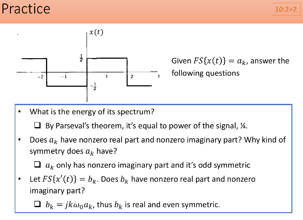
Example 2: Antisymmetric Periodic Square Wave (value +1 for 0<t<T0/2, -1 for −T0/2<t<0)
a0=0
ak=jπk1(1−(−1)k)={jπk20for odd kfor even k,k=0
This is an odd harmonic signal (only contains odd harmonics).
Example 3: Symmetric Periodic Square Wave (value 1 for −T0/4<t<T0/4, 0 for T0/4<∣t∣<T0/2, assuming T1=T0/4 in the slide’s general formula context for pulse width)
The slide shows ak={1/2,πksin(πk/2)k=0k=0
This specific formula corresponds to a square wave that is 1 for half its period and 0 for the other half, centered differently or having different height/duty cycle than typical examples.
A more standard symmetric square wave (period T0) would have ak=kπsin(kω0T1)=kπsin(kT02πT1) with 2T1 being the pulse width. The formula on the slide implies T1=T0/4 and height 1.
The phase spectrum is changed dramatically compared to the antisymmetric case due to the shift in the signal’s position.
X. Summary for Evaluating the FS Spectrum
If the signal is sinusoidal, use Euler’s formula.
cosφ=2ejφ+e−jφsinφ=2jejφ−e−jφ
If not sinusoidal, use the analysis equation:
a0=T01∫T0xT0(t)dt (the average of the signal in one period).
ak=T01∫T0xT0(t)e−jkω0tdt.
XI. Convergence of Fourier Series
A square wave (discontinuous) can be constructed by adding “enough” continuous complex exponential functions.
Partial Sum:xN(t)≜∑k=−NNakejkω0t
We want to show limN→+∞xN(t)=x(t).
Error Signal:eN(t)≜xN(t)−x(t)
FS representation converges if limN→∞eN(t) is zero under a certain criterion.
Two Convergence Criteria:
Energy Convergence:limN→∞∫T∣eN(t)∣2dt=0 (the difference signal has zero energy).
Pointwise Convergence:limN→∞eN(t)=0 for every t∈R.
Pointwise convergence is stronger than energy convergence and implies it.
Fourier Series Convergence Theorem #1 (Energy Convergence):
If a periodic signal has finite energy over a single period (i.e., ∫T∣x(t)∣2dt<∞), then its Fourier series partial sum converges to the signal subject to an error of zero energy.
The difference x(t)−∑k=−∞∞akejkω0t, if existent, must reside on a finite set of time indexes with a finite value.
Fourier Series Convergence Theorem #2 (Pointwise Convergence):
If a periodic signal satisfies the Dirichlet conditions, then its Fourier series partial sum converges to the signal pointwisely, except at points of discontinuity.
At points of discontinuity, the Fourier series converges to the average value of the signal on either side of the discontinuity.
Dirichlet Conditions (all three must be satisfied):
x(t) must be absolutely integrable over a single period: ∫T∣x(t)∣dt<∞. 绝对可积
x(t) must have a finite number of maxima(极大值) and minima (极小值) during a single period (finite total variation). 有限个极值点,可以理解为有限次振荡
x(t) must have a finite number of discontinuities during a single period, and each of these discontinuities must be finite.(所有的间断点都必须是第一类间断点) 有限个第一类间断点
Most practical signals (e.g., speech signals, image signals) satisfy all 3 Dirichlet conditions.
XII. Gibbs Phenomenon (or Gibbs Ringing)
When approximating a signal with discontinuities using a finite Fourier series sum (xN(t)), ripples appear near the discontinuities.
The maximal amplitude of these ripples does not decrease with increasing N. It overshoots by about 9% of the jump.
The width of the ripples continuously decreases with increasing N.
If N=∞, the ripple width becomes 0, so effectively no ripples are present. However, for any finite N, there is always an interval near the discontinuity where ripples reside.
This is due to the nonuniform rate of convergence of the Fourier series near discontinuities.
Gibbs phenomenon can be observed in medical images and natural images.
Since the integral ∫−∞∞e−jωτh(τ)dτ does not depend on t, we can define it as H(jω).
So, the output is y(t)=H(jω)ejωt.
Here, H(jω)≜∫−∞∞e−jωτh(τ)dτ is the eigenvalue associated with the eigenfunction ejωt.
This eigenvalue, H(jω), is known as the frequency response of the LTI system and depends on frequency ω and the system’s impulse response h(τ), but not on time t.
II. Frequency Domain Analysis of LTI Systems
A. Response to Periodic Signals
If a periodic input signal xT0(t) is represented by its Fourier series:
xT0(t)=k=−∞∑+∞akejkω0t
where ejkω0t are eigenfunctions of the LTI system.
The response of the LTI system T{⋅} to this arbitrary periodic signal is:
y(t)=T{xT0(t)}=T{k=−∞∑∞akejkω0t}
Using linearity and the eigenfunction property T{ejkω0t}=H(jkω0)ejkω0t:
If we let bk=akH(jkω0), then the output is also a periodic signal with the same period:
y(t)=k=−∞∑∞bkejkω0t
The output spectrum is bk=akH(jkω0).
H(jkω0) describes how the system modifies each harmonic component of the input signal. It’s a sampled version of the continuous frequency response H(jω) at discrete harmonic frequencies ω=kω0.
B. Two Methods to Analyze an LTI System
Time Domain:
Input: x(t)=∫−∞∞x(τ)δ(t−τ)dτ (sum of impulses)
System: Impulse response h(t)
Output: y(t)=∫−∞∞x(τ)h(t−τ)dτ (convolution)
Frequency Domain (for periodic inputs):
Input: x(t)=∑k=−∞∞akejkω0t (sum of exponentials)
System: Frequency response H(jω)=∫−∞∞e−jωτh(τ)dτ, sampled at kω0⇒H(jkω0)
Output: y(t)=∑k=−∞∞(akH(jkω0))ejkω0t (sum of exponential responses)
C. Rationale for Frequency-Domain Analysis
Computational Advantages: Multiplication in the frequency domain is often simpler than convolution in the time domain.
Example: Input x(t)=cos(32t) and impulse response h(t)=πtsin(t).
The frequency response is H(jω)=∫−∞∞e−jωτπτsin(τ)dτ={1,0,if ∣ω∣<1otherwise (This is a standard Fourier Transform pair for an ideal low-pass filter scaled).
For x(t)=cos(32t), ω0=32. The Fourier series coefficients ak are non-zero only for k=−1 and k=1 (specifically, a1=a−1=1/2).
The relevant system responses are at H(j1⋅32)=H(j32) and H(j(−1)⋅32)=H(−j32).
Since ∣±32∣<1, H(j32)=1 and H(−j32)=1.
The output spectrum bk=akH(jkω0) will be b1=a1⋅1=1/2 and b−1=a−1⋅1=1/2.
Thus, y(t)=x(t).
Critical Insights: It shows how the system modifies each harmonic.
If ∣H(jkω0)∣>1, the kth harmonic is strengthened.
If ∣H(jkω0)∣<1, the kth harmonic is attenuated.
This leads to the concept of filtering.
III. Filtering (滤波)
A. Definition
Filtering is essentially spectral editing. An LTI filter is an LTI system whose frequency response H(jω) is shaped to change the input spectrum by multiplication (bk=akH(jkω0)).
Example: Lowpass Filter (低通滤波器)
H(jω)=1 for ∣ω∣<ωc (Passband)
H(jω)=0 for ∣ω∣>ωc (Stopband)
For harmonics kω0 within (−ωc,ωc), ak is preserved (bk=ak).
For harmonics outside this range, ak is suppressed (bk=0).
Low-frequency harmonics are preserved; high-frequency ones are eliminated.
B. Types of LTI Filters
Frequency-selective filters (频率选择性滤波器) or ideal filters (理想滤波器): Pass certain frequencies and completely eliminate others.
Ideal Lowpass Filter (低通): Kills high frequencies. H(jω)=1 for ∣ω∣<ωc, 0 otherwise.
Ideal Highpass Filter (高通): Kills low frequencies. H(jω)=1 for ∣ω∣>ωc, 0 otherwise. (The image shows passband outside (−ωc,ωc) but it should typically be symmetric, passing ∣ω∣>ωc).
Ideal Bandpass Filter (带通): Passes a specific band of frequencies. H(jω)=1 for ωc1<∣ω∣<ωc2, 0 otherwise.
Frequency-shaping filters (频率成形滤波器): Change the shape of the input spectrum without completely passing or killing harmonics.
Example: Differentiator (y(t)=dtdx(t)).
Its frequency response is H(jω)=jω.
Magnitude: ∣H(jω)∣=∣ω∣.
High-frequency components are strengthened, and low-frequency components are suppressed.
C. Filter Questions
Is an edge detector a low-pass or high-pass filter?
Edges are determined by high-frequency harmonics. Since edge detectors strengthen these, they are high-pass filters.
What filter to use to keep only harmonics within 10-500Hz for an EMG signal?
This requires a bandpass filter because it preserves a specific band of frequencies, eliminating those below 10Hz and above 500Hz.
Looking at this table of properties for continuous-time Fourier series, I’ll convert it to markdown format with proper LaTeX formula syntax:
Property
Section
Periodic Signal
Fourier Series Coefficients
x(t) Periodic with period T and y(t) fundamental frequency ω0=2π/T
ak bk
Linearity
3.5.1
Ax(t)+By(t)
Aak+Bbk
Time Shifting
3.5.2
x(t−t0)
ake−jkω0t0=ake−jk(2π/T)t0
Frequency Shifting
ejMω0t(=ejM(2π/T)t)x(t)
ak−M
Conjugation
3.5.6
x∗(t)
a−k∗
Time Reversal
3.5.3
x(−t)
a−k
Time Scaling
3.5.4
x(αt),α>0 (periodic with period T/α)
ak
Periodic Convolution
∫Tx(τ)y(t−τ)dτ
Takbk
Multiplication
3.5.5
x(t)y(t)
ak∗bk=∑l=−∞∞albk−l
Differentiation
dtdx(t)
jkω0ak=jkT2πak
Integration
∫−∞tx(t)dt (finite valued and periodic only if a0=0)