Chapter6 Time & Frequency Characterization
Frequency Response
Phase of Frequency Response
A filter’s frequency response can be uniquely represented by its magnitude and phase.
Linear phase shift
- If the phase shift is linear, then the input signal would be shifted in time because of time-shifting property.
- This means a linear phase shift would delay the input signal, which is usually undesired.
- Therefore, you want to minimize the slope of the phase shift in order to minimize delay.
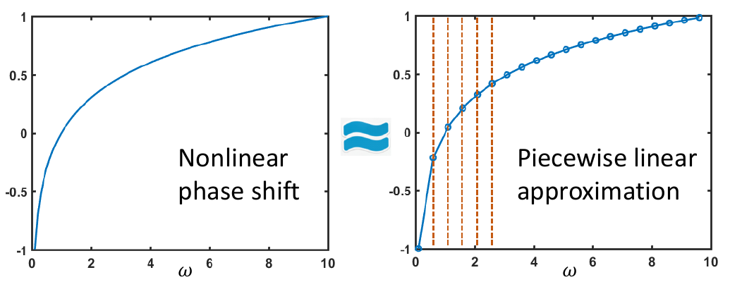
Nonlinear phase shift: group delay
What if the phase shift is nonlinear?
- A nonlinear phase shift would shift different harmonic by a different amount, which results in distortion of the original signal.
- We can use Piecewise linear approximation to deal with nonlinear phase shift
How to deal with phase shift?
- Phase shift is common for analog filters
- Therefore, delay and distortion are common for analog filters
- Delay is usually better than distortion. Therefore, what we can do is to ensure the phase shift is as linear and small as possible in the passband
Question: if you want to reduce the delay, how would you change R and C?
- Use as little R and C as possible
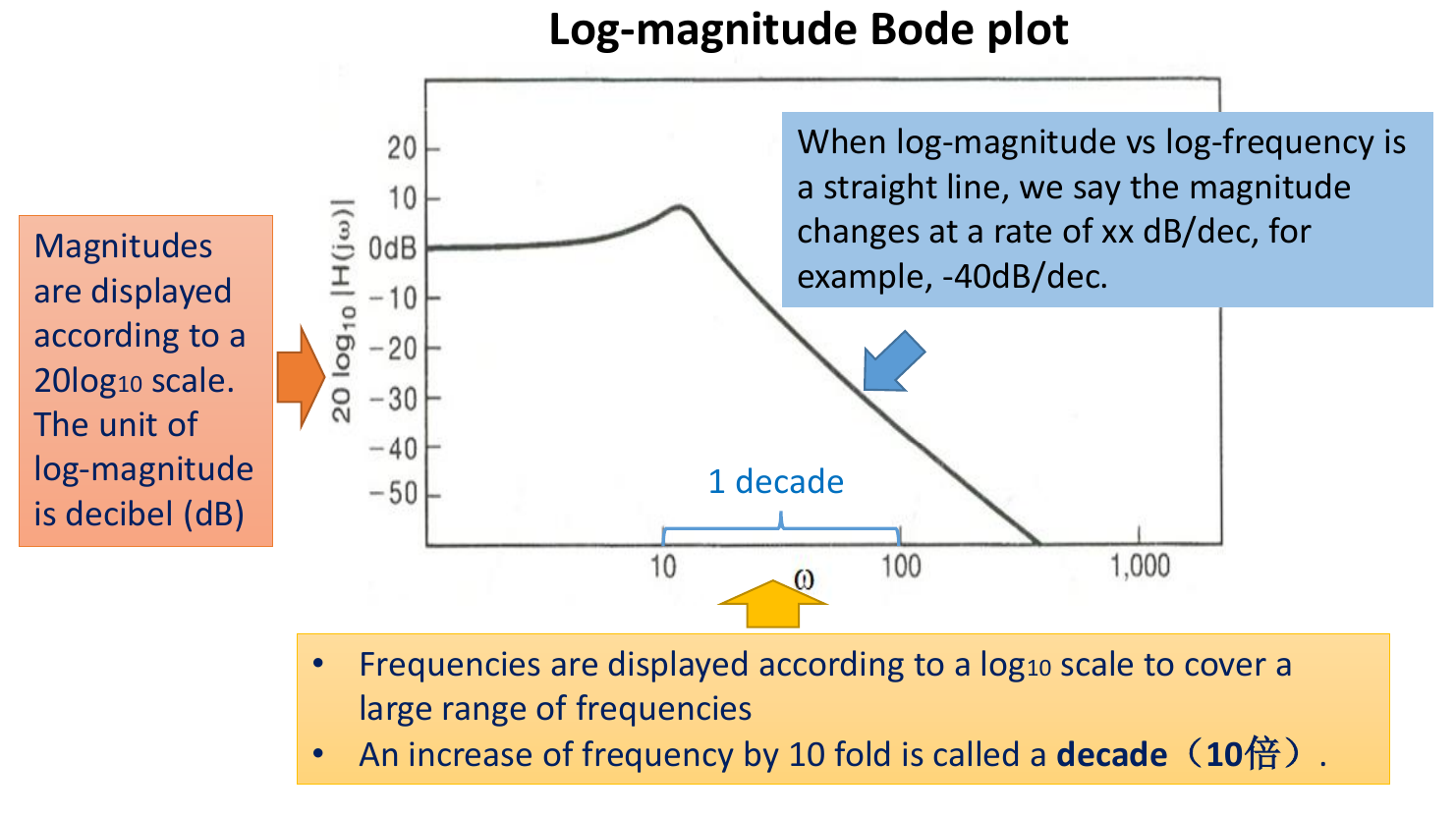
Gain of a filter/system
- 由于增益的变化很大,频率的变化范围也很大,所以需要使用对数单位才能更好的分析
- We need a tool that covers larger ranges of frequencies and magnitudes ⟹ Bode plot(波特图)
Bode Plot 波特图
-
The magnitude Bode plot shows the relationship between (log-magnitude) and (log-frequency)
-
幅度(纵轴)使用 作为单位
-
频率(横轴)以对数分布
-
下降段/上升段可以近似为直线时,标出变化率 (dB/10倍频)
-
- The phase Bode plot shows the relationship between the phase and (log-frequency)

Notes about the Bode plot
- Note that the Bode plot for real signals/impulse responses usually shows only the positive frequency domain since the spectrum is conjugate symmetric.
- Another advantage for Bode plot is it transforms multiplication to addition.
- If we have the input spectrum and frequency response, we can add their corresponding Bode plots to generate the Bode plot for the output spectrum.

Decibels of passband, transition, and stopband
Some common decibel values and their indications:
- 0dB – a gain of 1 [passband].
- -20dB – a gain of 1/10 [transition band].
- -40dB – a gain of 1/100 [effectively zero; stopband].
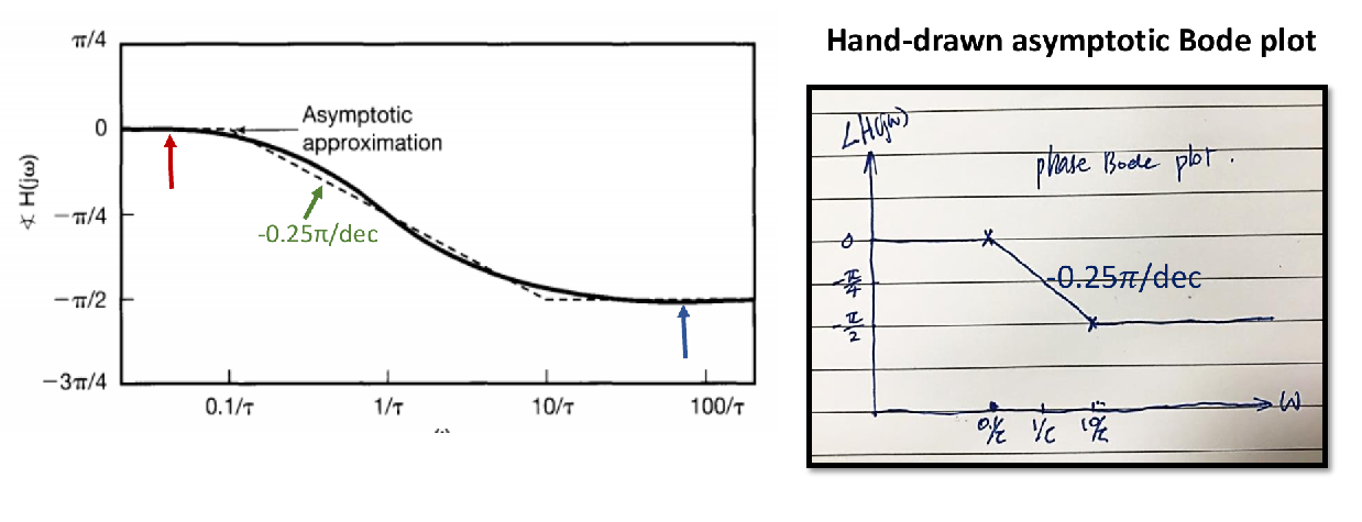
The asymptotic Bode plots
Second-order LCCDE filters
- The standardized equation: ,
- Derive the frequency response:
- How to generate the asymptotic Bode plot for -order systems?
- Note that
- That is, a -order LCCDE system is a cascading of two -order LCCDE systems and .
- Then, the asymptotic Bode plots for the cascaded system is simply a sum of the Bode plots for the two subsystems:
Considerably simplifies evaluation of asymp. Bode plot for higher-order systems
时频分析与滤波器设计
一、滤波器设计概述
生物医学信号(如ECG、EEG、EMG)通常非常微弱,在进行分析前需要经过差分放大、滤波、主放大和ADC(模数转换)等步骤 [cite: 6, 7, 8]。本讲座主要关注模拟LCCDE(线性常系数微分方程)系统的设计、评估和分析,特别是其中的滤波环节 [cite: 8]。
设计一个“完美”的滤波器,即信号无失真且噪声完全消除,是理想情况 [cite: 9, 10]。但在实际设计中,主要面临以下三个约束 [cite: 11, 14]:
- 频率响应的相位:非零相位如何影响输入频谱 [cite: 11]。
- 频率响应的幅度:如何设计具有更陡峭过渡带的滤波器 [cite: 12]。
- 时频折衷:“完美”的频率响应可能对应“不完美”甚至“不可行”的时域冲激响应 [cite: 13]。
二、频率响应的相位特性
滤波器的频率响应 可以唯一地由其幅度和相位表示 [cite: 15]:
- 幅度响应 (系统增益):通过乘法影响输入频谱的幅度 [cite: 18]。
- 相位响应 (系统相移):通过加法影响输入频谱的相位 [cite: 21]。
1. 线性相移
-
如果相移是线性的,例如 ,则根据傅里叶变换的时移特性,输出信号是输入信号在时域上的延迟 [cite: 23]:
-
通常希望最小化相移的斜率以减少延迟 [cite: 25]。
2. 非线性相移:群延迟
- 非线性相移会导致不同频率分量产生不同的延迟,从而造成信号失真。
- 群延迟(Group Delay)描述了不同频率成分的延迟情况,其更像是失真而非简单的延迟。
- 例如,在某个LTI系统中,50Hz的谐波可能延迟0.10s,而150Hz的谐波延迟0.06s,300Hz的谐波延迟0.02s。
3. 处理相移
- 由于模拟滤波器普遍存在相移,延迟和失真也相应常见 。
- 通常延迟比失真更容易接受,因此设计目标是确保在通带内相移尽可能线性且尽可能小。
- 例如,对于RC电路,其相移为 。减小R和C的值可以减小延迟。
三、频率响应的幅度特性与波特图
1. 系统增益
- 滤波器设计的核心目标之一是调整电路参数,使系统增益符合设计要求。
2. 波特图 (Bode Plot)
由于滤波器分析涉及的频率范围和增益变化范围可能很大,需要使用波特图进行更有效的显示和分析。
-
对数幅度波特图:显示 (单位:分贝,dB)与 (对数频率)的关系。频率增加10倍称为一个“十倍频”(decade)。
- 手画波特图时,简化成直线
- 直线的转折点为截止频率点
- 标出通带,过渡带,阻带的交界点在图上的位置
- 下降段需要标出下降速率,例如 -20dB/dec (-20dB/十倍频)
-
相位波特图:显示 (单位:弧度,rad)与 的关系 [cite: 41]。
波特图的特点:
- 对于实信号/冲激响应,通常只显示正频率部分,因为频谱具有共轭对称性(幅度偶对称,相位奇对称)。
- 将乘法运算转换为了加法运算:
- 这对于串联系统的增益评估非常有用。
常用分贝值及其含义 [cite: 48]:
- 0dB:增益为1(通带)。
- -20dB:增益为1/10(过渡带)。
- -40dB:增益为1/100(有效为零,阻带)。
四、一阶LCCDE滤波器分析
1. 标准形式与频率响应
-
一阶LCCDE滤波器的标准方程通常可以表示为:
-
其中 称为系统的时间常数。例如,对于RC低通滤波器, 。
-
其频率响应:
-
对数幅度和相位分别为 [cite: 55]:
-
这个频率响应其实就是一个标准的一阶低通滤波器
-
截止频率
2. 精确波特图分析
- 所有一阶低通滤波器初始增益为1(0dB),初始相位为0 [cite: 58]。
- 时间常数 越大,通带越窄 [cite: 58]。
- 大约在 处,增益开始下降,下降速率约为 -20dB/decade [cite: 59]。
- 相位从0开始下降,最终达到 。在通带内,较大的时间常数通常导致较大的相移斜率,从而产生较大的延迟 [cite: 59]。
3. 渐近波特图 (Asymptotic Bode Plot)
为了方便手动绘制,引入渐近波特图。
-
幅度渐近线:
- 两条直线在转折频率(break frequency) 处相交,该频率也是一阶LCCDE滤波器的通带截止频率。
-
相位渐近线:
- 转折点: 和
- 最终的图是三条直线段:两边水平直线,中间为连接两个转折点的下降直线(斜率恒定且为负)
- 在 处,相位约为 。
![image-20250515190157233]()
4. 一阶滤波器分析总结 [cite: 70]
- 通带截止频率为 。
- 过渡带的衰减率为 -20dB/decade,需要2个十倍程才能从通带转换到阻带。
- 在 范围内存在线性相移,导致相应谐波的延迟 [cite: 71]。
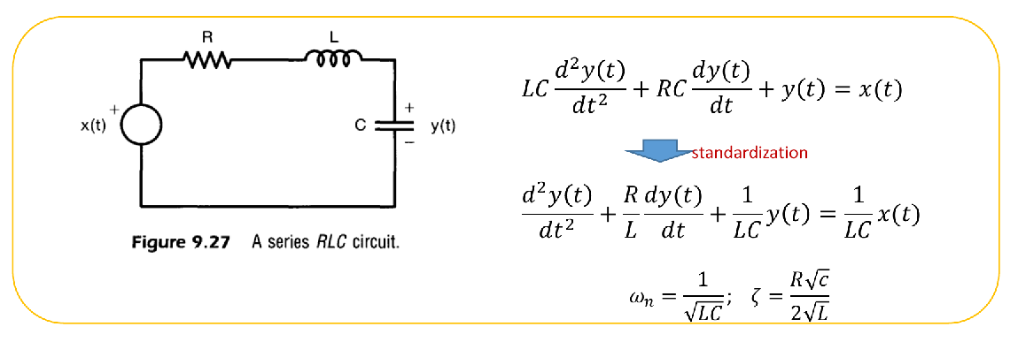
五、二阶LCCDE滤波器分析
1. 标准形式与频率响应
- 二阶LCCDE滤波器的标准化方程为:
-
其中 是无阻尼自然频率, 是阻尼比。
-
其频率响应为 [cite: 74]:
-
例:对于串联RLC电路,可以对电路方程进行如下标准化
- 从而得到结论:
2. 渐近波特图
二阶系统可以看作是两个一阶系统的级联 [cite: 76]。
利用求根公式 对频率响应进行拆分
where:
因此,其渐近波特图是两个子系统波特图的叠加 [cite: 77]:
例如,当 时,系统可以分解为两个相同的一阶环节,转折频率均为 [cite: 79, 80]:
-
幅度渐近线:
- 当 时,增益为 0dB + 0dB = 0dB。
- 当 时,衰减率为 -20dB/decade + (-20dB/decade) = -40dB/decade。
-
相位渐近线 (对于 ):
- 当 时,相位为 0rad + 0rad = 0rad。
- 当 时,相位为 。
- 过渡带的斜率为 。
3. 二阶滤波器分析总结
- 通带截止频率为 [cite: 84]。
- 过渡带的衰减率为 -40dB/decade,比一阶滤波器快两倍,因此二阶滤波器更接近“理想”滤波器 [cite: 85, 86]。
- 较小的 值可以减少通带内的相移,从而减少延迟,但可能会在转折频率附近产生幅度尖峰和更剧烈的相位变化 [cite: 86, 88]。 决定转折频率和通带截止频率,而 主要影响相位过渡的陡峭程度和幅度响应在转折频率附近的形状 [cite: 88]。
六、滤波器的时频折衷
1. 理想滤波器的问题
- 理想滤波器(例如,频率响应为矩形窗)的冲激响应在时域上是无限长的(如sinc函数)。
- 这意味着要实现理想滤波,必须使用过去和未来的全部输入信号,这对于实时应用是不可行的。
2. 时频折衷
- 如果需要实时处理,就必须放弃理想滤波的目标,即牺牲频域性能以换取时域性能 [cite: 96, 97]。
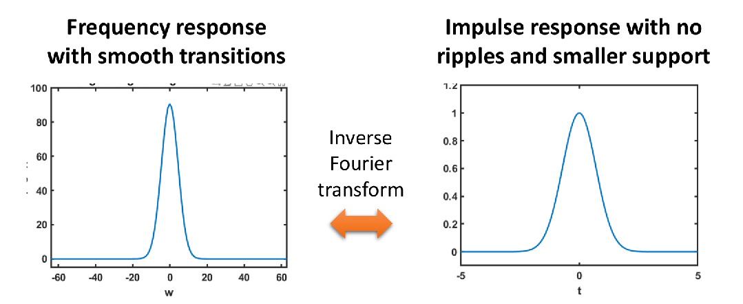
- 频域中的较平滑的过渡(smooth transitions)可以消除时域中不断延伸的波纹,减小时域的依赖区间
- 这种时域性能和频域性能之间的折衷称为时频折衷 [cite: 98]。
其他折衷 [cite: 99]:
- 更强的滤波(更窄的过渡带)通常意味着更慢的响应速度(在阶跃响应中体现为更长的响应时间)。
- 频域中急剧的过渡(sharp transition)会导致时域中的振铃现象(Gibbs现象)。
3. 非理想滤波器
为了缓解时频折衷,实际中采用非理想滤波器,它们通过在频域上做一些妥协来改善时域特性
- 允许频域中较平缓的过渡,以减少时域中的波纹,从而减小了时域信号的依赖区间。
- 允许频域中存在波纹(ripples),以提高时域响应速度(基于对偶性),从而提高实时性。
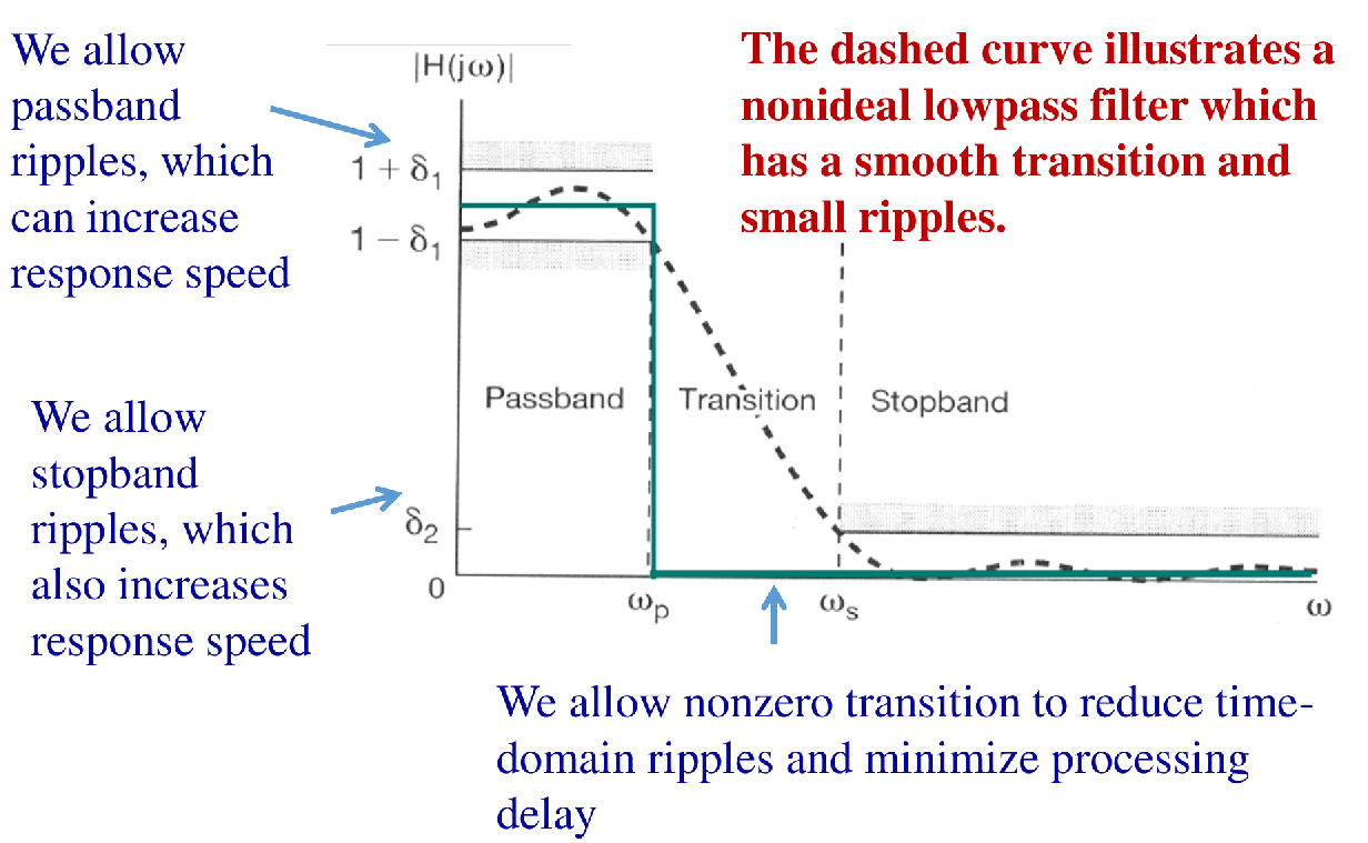
非理想滤波器的特性 [cite: 104, 105]:
- 通带波纹 ():允许通带内幅度存在小范围波动,可以提高响应速度。
- 阻带波纹 ():允许阻带内存在一定的信号泄露,也可以提高响应速度。
- 过渡带 ( 到 ):允许非零的过渡带宽,以减少时域振铃并最小化处理延迟。
4. 常见的非理想滤波器 [cite: 106]
- 巴特沃斯滤波器 (Butterworth):最大平坦幅度滤波器,纹波少,时域响应慢。
- 切比雪夫滤波器 (Chebyshev):由于过渡带更快,纹波较多;由于频域存在一些纹波,响应速度较快。
- 椭圆滤波器 (Elliptic):由于过渡带非常陡峭,时域纹波最多;由于频域纹波很多,响应速度最快。
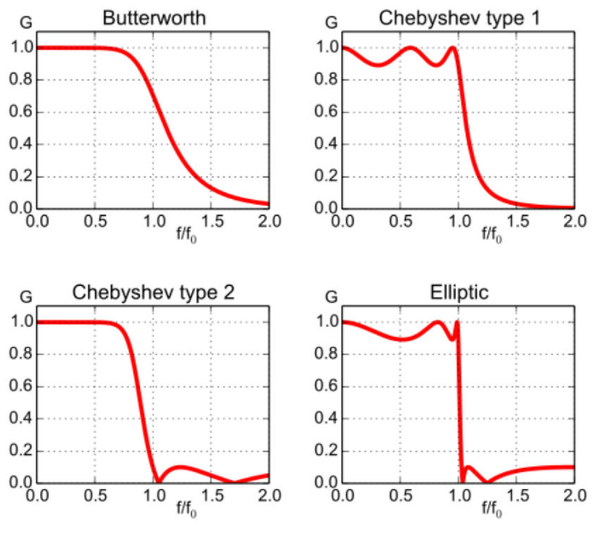
例如,一个三阶巴特沃斯低通滤波器的增益公式为 [cite: 107]。
